
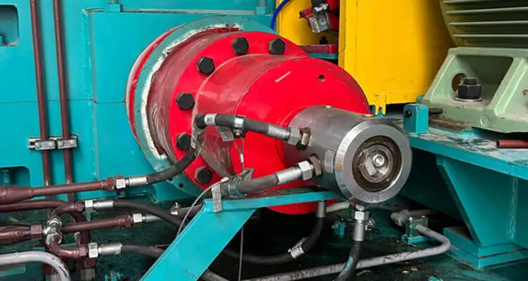
Rotary unions used in CNC rotary tables and hydraulic workholding systems are often selected based on working pressure, rotational speed, and the number of passages. However, some design problems are not obvious when looking at the rotary union alone. They emerge only after the union is integrated into the complete hydraulic fixture and machine tool system.
Incorrect passage planning can complicate hydraulic control. Excessive drag torque can affect rotary table performance. High clamping pressure may not always need to pass through the rotary union, and even minor leakage between hydraulic and pneumatic circuits can interfere with workpiece seating detection.
Based on practical engineering considerations, this article examines four issues that deserve attention before specifying a multi-passage rotary union for CNC hydraulic workholding. WayDun Team wrote a complete guide about rotary union.
Table of Contents
Toggle1. Counting Passages: Start with the Hydraulic Circuit, Not the Number of Cylinders
One common design mistake is to determine the number of rotary union passages simply by counting the hydraulic cylinders on a fixture.
The number of passages should instead be determined by the number of independent fluid connections that must cross the stationary-to-rotating interface. The required configuration depends on cylinder type, control logic, valve location, and whether different actuators need to operate independently.
Consider the following examples.
Four single-acting cylinders with independent control
If each cylinder requires its own independently controlled supply connection, four passages may be needed. The final number depends on the hydraulic circuit and how return flow is handled.
Two double-acting cylinders with independent control
Each cylinder typically requires an A and a B working line. If the directional control valves remain on the stationary side, four independent working passages may be required to control both cylinders separately.
Multiple cylinders operating together
If several cylinders always perform the same function and can share a common hydraulic circuit, the number of passages may be reduced. Another option is to install directional control valves or a valve manifold on the rotating side, allowing common pressure and return lines to pass through the rotary union.
However, reducing the number of passages this way introduces other considerations, including rotating-side space, valve integration, control wiring, flow requirements, and maintenance access.
The key distinction is between the number of actuators and the number of independently controlled hydraulic circuits. They are related, but they are not necessarily the same.
Before selecting a rotary union, finalize the hydraulic schematic and confirm the required motion sequence, independent control functions, and valve locations. Only then should the number of passages be determined.
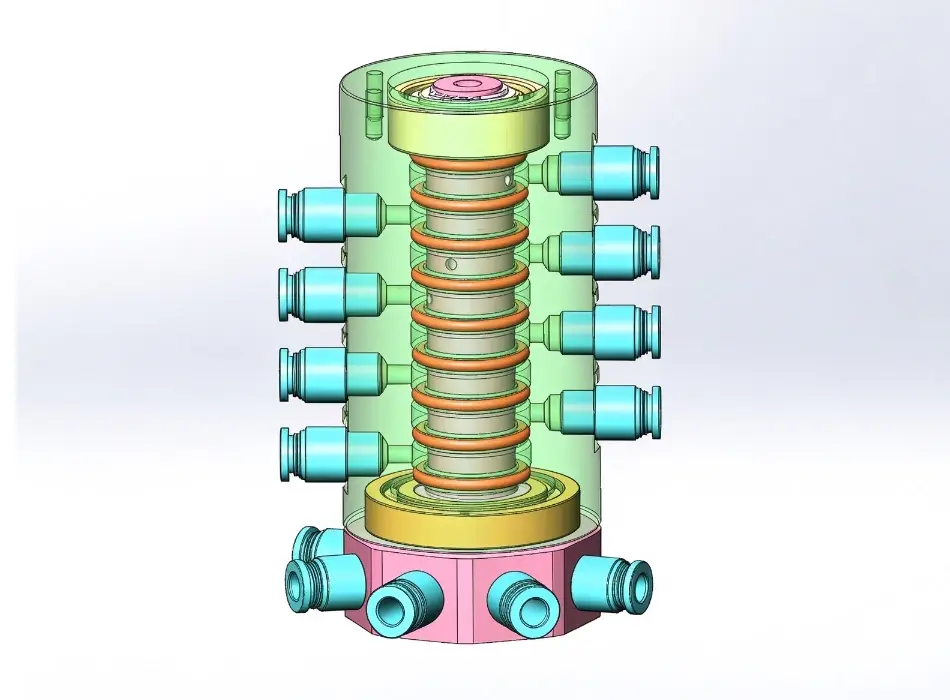
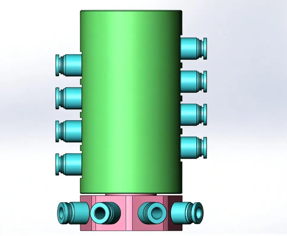
2. Rotary Union Drag Torque: An Important Factor in CNC Rotary Table Design
For a CNC machine equipped with a fourth-axis rotary table, drag torque is an important parameter that can be overlooked during rotary union selection.
A rotary union must maintain fluid separation across a rotating interface while allowing relative rotation. The resulting resistance depends on the sealing principle, seal geometry, bearing arrangement, pressure, speed, temperature, and other operating conditions.
In some designs, increasing pressure increases the load on dynamic sealing surfaces, which can raise friction and rotational resistance. A larger dynamic seal diameter can also affect friction torque, depending on the seal design and its effective contact load.
These relationships are not universal. Pressure-balanced mechanical seals, for example, are specifically designed to reduce the effect of fluid pressure on the effective seal load.
Why does this matter for a CNC rotary table?
The rotary table’s servo drive must overcome not only the resistance associated with the table and fixture, but also the additional resisting torque introduced by the rotary union and other connected components. If the union’s drag torque is underestimated, the available drive torque may be lower than expected, particularly during demanding indexing operations.
When evaluating a rotary union, consider the following:
- Actual working pressure: Do not assume that torque measured at zero pressure represents torque under hydraulic operating conditions.
- Operating speed and temperature: Friction and seal behavior may change as the operating conditions change.
- Servo torque margin: Check the additional resistance against the rotary table’s available drive torque, including acceleration and other mechanical loads.
If the machine has limited drive torque margin, ask the rotary union manufacturer WayDun Technology for torque data under the intended operating conditions rather than relying exclusively on a catalog’s minimum or zero-pressure torque figure.
The practical lesson is simple: a rotary union that meets the required pressure and speed ratings is not automatically the best choice for a precision rotary table. Its drag torque must also be compatible with the machine’s drive system.
3. High Clamping Pressure Does Not Always Require High Pressure Through the Rotary Union
Hydraulic workholding systems sometimes require a high clamping pressure to generate sufficient force within a compact fixture. A straightforward approach is to select a rotary union rated for the full clamping pressure.
However, this is not the only possible design solution.
Where the hydraulic architecture permits, a pressure intensifier can be installed on the rotating side of the fixture. The system can then supply lower-pressure oil through the rotary union and increase the pressure locally for the clamping circuit.
A simplified arrangement is:
Low-pressure hydraulic supply → rotary union → rotating-side pressure intensifier → high-pressure clamping circuit
This approach can reduce the pressure that the rotary union itself must handle while still providing the higher pressure required by the clamping components.
The potential benefit is particularly relevant to compact hydraulic fixtures that require high pressure but relatively small oil volumes.
However, this arrangement is not suitable for every application. Before adopting it, the designer should verify several factors:
Clamping force: The intensified output pressure must generate sufficient force for the clamping cylinders and withstand the expected machining loads.
Required oil volume: A pressure intensifier trades flow volume for higher pressure. The available high-pressure output volume must be sufficient for the cylinder displacement and required stroke.
Cycle time: The intensifier and upstream hydraulic supply must deliver the required clamping and release speeds within the machine’s operating cycle.
Pressure holding and circuit control: Check valves, pressure monitoring, relief protection, and the overall hydraulic circuit must be designed to maintain safe and reliable clamping.
Component pressure ratings: The intensifier’s high-pressure side, clamping cylinders, fittings, and connecting passages must be rated for the maximum possible output pressure.
This means that the question is not simply whether to choose a higher-pressure rotary union. It is whether the pressure-generation stage should be located before or after the rotating interface.
A well-planned hydraulic circuit may reduce the demands placed on the rotary union, but the complete system must be evaluated to confirm that the solution meets the required clamping force, oil volume, and operating cycle.

4. Hydraulic and Pneumatic Passages: Do Not Overlook Cross-Contamination
Many CNC hydraulic fixtures use hydraulic oil for clamping and compressed air for workpiece seating detection. The hydraulic and pneumatic circuits may need to pass through the same multi-passage rotary union.
A rotary union designed for multiple media can separate these circuits under its specified operating conditions. However, the designer should not assume that hydraulic and pneumatic passages will remain completely isolated under every possible condition, including seal wear or failure.
Even a small amount of hydraulic oil entering a pneumatic seating-detection circuit can contaminate a restrictor, orifice, pressure sensor, or other sensitive component. Depending on the detection method, this may cause unstable readings, delayed responses, or false seating signals.
For example, if a workpiece has not fully contacted its locating surface but the pneumatic circuit produces an incorrect pressure response, the machine may proceed with an unsuitable clamping condition. The resulting problem is not limited to the rotary union: it can affect machining accuracy and process reliability.
For hydraulic-pneumatic applications, several design considerations are important.
Separate the media appropriately. Select a rotary union designed for the actual oil and air combination, with compatible sealing materials and suitable passage isolation.
Evaluate an intermediate separation or leakage-drain passage. Depending on the rotary union’s design, a dedicated passage between the hydraulic and pneumatic circuits can help collect and discharge leakage before it reaches the other circuit.
Design the drain path properly. A leakage-drain passage must have a suitable outlet and should not be blocked or subjected to backpressure that could undermine its intended function. An intermediate passage alone does not guarantee that cross-contamination cannot occur.
Protect the seating-detection circuit. Confirm that the air circuit remains suitable for the sensitivity and response requirements of the detection system, and consider how leakage will be identified during operation or maintenance.
Integrated with electrical slip ring. Rotary joint can combine with electrical slip ring, Excellent integrators can integrate gas, liquid, optical signals, electrical signals and power into one rotary connector.
The appropriate solution depends on the rotary union’s sealing arrangement, the pressure relationship between adjacent passages, and the requirements of the detection system. A separation or drain passage is therefore a design option to evaluate, not a universal requirement for every hydraulic-pneumatic rotary union.
The important point is that a combined oil-and-air rotary union should be evaluated not only for its ability to transmit both media, but also for how it manages leakage and protects the functions connected to each passage.
Final Checks Before Specifying a Rotary Union
Before releasing a design for a CNC rotary table or hydraulic workholding fixture, confirm the following:
- The hydraulic schematic and actuator sequence are finalized.
- The required number of independent passages has been established.
- Drag torque has been evaluated under the intended operating conditions.
- The rotary union’s pressure rating is matched to the actual circuit architecture.
- Any rotating-side pressure intensifier has sufficient output pressure and oil volume.
- Hydraulic and pneumatic passages have suitable isolation, with leakage drainage considered where necessary.
- The mounting arrangement and external connections comply with the manufacturer’s installation requirements.
These checks help prevent problems that may not be apparent from the rotary union’s basic specifications alone.
Conclusion
Reliable rotary union design requires more than matching pressure, speed, and connection dimensions. For CNC hydraulic workholding, the hydraulic circuit architecture, rotary table drive capability, location of pressure intensification, and separation of oil and air circuits can all influence the performance of the complete machine.
Addressing these issues early in the design process can help avoid unnecessary complexity, reduce the risk of premature component problems, and improve system reliability.
When selecting a standard or custom rotary union, provide the hydraulic schematic, passage requirements, working pressure, flow rate, rotational speed, installation dimensions, and any special requirements for pneumatic seating detection. With these details established, the rotary union can be specified around the actual application rather than selected by pressure rating alone.