
A rotary union, also called a rotary joint, transfers a liquid or gas from a stationary supply line into rotating equipment without interrupting rotation. In a typical machine-tool setup, coolant moves from a pump through the union and into a rotating spindle. The challenge is to keep the flow path open while controlling leakage where stationary and rotating components meet.
This article focuses on fluid transfer. Electrical power and signals are normally transferred through slip rings, although an integrated assembly can combine a rotary union and a slip ring when both fluid and electrical connections are needed.
Table of Contents
ToggleHow Does a Rotary Union Work?
In a common machine-tool design, the process follows four steps:
- The medium enters through a stationary connection. Coolant, oil, air, or another compatible medium arrives from a pump or supply line.
- Internal passages guide the flow. Channels inside the union direct the medium toward the rotating assembly. In a multi-passage design, separate routes carry different media or serve independent circuits.
- The sealing system contains the medium. Seals control leakage at the interface while allowing the rotor and stationary element to move relative to each other.
- The medium exits into the equipment. The flow continues through the rotor or outlet connection and into the spindle or another rotating component.
This is a common arrangement, not a universal layout. Depending on the equipment and union design, either the shaft or the housing may rotate. The flow direction and port arrangement can also vary, but the central principle remains the same: transfer the medium across a rotary interface while maintaining the required seal.
The Parts That Keep the Flow Moving
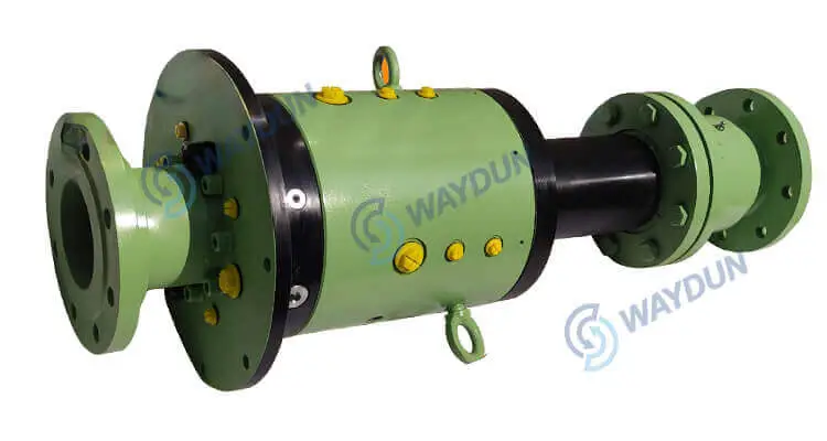
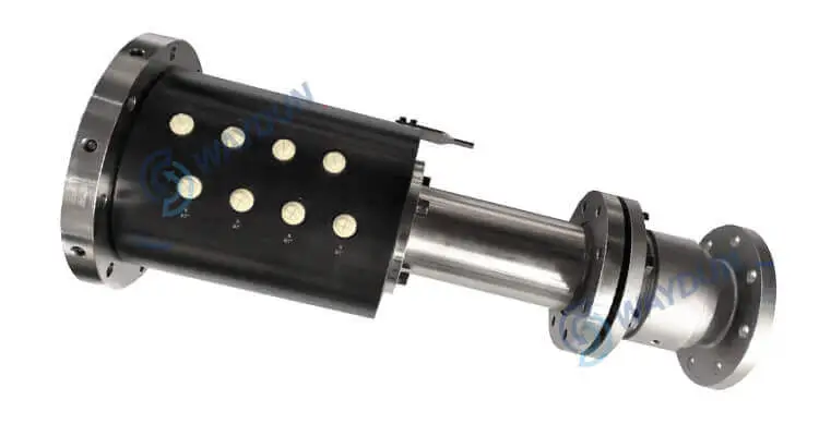
- Rotor or shaft: In a typical spindle application, it turns with the machine and carries the medium toward the rotating equipment.
- Housing and stationary element: These connect the union to the supply line and support the sealing arrangement. Their exact relationship to the rotating assembly depends on the design.
- Internal passages and ports: These define how the medium enters, travels through, and leaves the union. Some designs use a central through-bore to provide a direct coolant path.
- Sealing system: This contains the medium and, in multi-passage units, separates one flow circuit from another.
- Bearings, where fitted: These support relative rotation and help maintain alignment. Bearingless unions are also used, so an internal bearing is not a universal feature.
How Does the Sealing System Work?
The seal is the critical interface because it must contain the medium while one component rotates relative to another. The mechanism depends on the union design. A soft dynamic seal may sit between the rotor and housing, while a mechanical face seal uses two precision-finished surfaces—one rotating and one stationary—to control the fluid boundary.
A balanced mechanical seal is designed to manage the force acting on the sealing faces and reduce excessive contact load. Other rotary unions use pressure-loaded carbon-graphite seals or a controlled clearance where a thin film of fluid provides lubrication. These approaches work differently and have different operating limits; they should not be treated as interchangeable.
In a multi-passage rotary union, seals also isolate neighboring flow circuits. If a seal wears, becomes contaminated, or operates beyond its intended conditions, the medium may leak externally or pass into another circuit. Seal performance therefore depends on more than the seal material alone: surface finish, pressure, speed, temperature, medium compatibility, and cleanliness all matter.
Why High Speed and High Pressure Make Sealing More Difficult
As rotational speed increases, the relative movement at the sealing interface rises. Depending on the seal design, this can increase friction and heat. At the same time, the seal must contain the fluid pressure without excessive leakage or wear. These demands are especially important in high-speed coolant unions used in machine tools.
A published example from WayDun’s machine-tool coolant-union literature describes sealing surfaces moving at nearly 5 m/s at 15,000 rpm while containing fluid pressure of 140 bar (2,030 psi). The catalog also describes precision-lapped sealing surfaces and silicon-carbide seal materials. These are manufacturer-specific design details, not general performance ratings for every rotary union. See the WayDun Technology machine-tool coolant-union for the published example.
What Changes in a Multi-Passage Rotary Union?
A single-passage union provides one route for a medium. A multi-passage unit carries two or more separate flows through the same rotating connection. Each circuit needs a defined path and suitable sealing between adjacent channels; otherwise, media could mix or pressure could be lost between passages. A through-bore may be added where the machine requires a central coolant path, but the number and layout of passages depend on the design.
For this reason, the number of passages is not just a port-count detail. It changes the internal layout and the demands placed on sealing. The pressure, speed, and media supported by a particular unit must be confirmed against that model’s specifications.
Applying the Working Principle to a Real Machine
The key question is not simply whether a rotary union can rotate. It is whether the union can maintain the required flow and sealing performance under the actual operating conditions. Coolant, cutting oil, air/oil mist used in minimum quantity lubrication (MQL), dry air, hydraulic fluid, and compressed air for clamping or sensing may all be handled by suitable designs, but compatibility should never be assumed across models.
When assessing a rotary union, the useful starting details are the medium, operating pressure, rotational speed, required flow, number of passages, connection arrangement, and available installation space. For a broader overview of rotary joint designs and product options, see our rotary union guide and product overview.