
Industrial machinery requires seamless 360° continuous rotation while transmitting power and data signals. Electrical slip rings—also known as electrical rotary joints, collector rings, or rotary electrical interfaces—are the essential components that bridge the gap between stationary structures and rotating systems. By utilizing a stator (fixed end) and a rotor (rotating end), these devices ensure uninterrupted electrical connections in wind turbines, robotics, and medical equipment.
Understanding the tribological behavior of electrical contact materials and executing precise preventative maintenance are critical to preventing signal degradation and costly downtime.
Table of Contents
ToggleClassification of Slip Ring Electrical Contact Materials (Brush & Friction Pair Materials)
Selecting the ideal electro-mechanical contact combination dictates the lifespan, current capacity and signal integrity of your rotary joint. Different engineering applications demand distinct specialized friction pairs.
Monofilament Gold Alloy Wire
Key Pros: Excellent structural stability, easy one-time bending formation, and superior wear resistance.
Key Cons: Reduced mechanical elasticity.
Design Philosophy: Engineers design these brush wires to be “soft” so they wear optimally against a harder ring surface, achieving an ideal tribological balance.
Composite Elastic Material and Gold Alloy Combination
Performance: This design pairs a mold-shaped elastic substrate with a gold alloy cladding to deliver exceptional spring resilience.
Precision Engineering: Custom-angled designs guarantee uniform contact force across every individual wire, yielding outstanding wear resistance at the interface.
Carbon Fiber and Silver Brush Wire Bundles
The Matrix: This system utilizes a “hard brush, soft ring” mechanism for optimized friction pairing.
Material Dynamics: The track uses silver as its primary ingredient due to its self-lubricating properties.
Trade-offs: To achieve a long service life, the ring diameter must be enlarged. However, larger diameters create wider tracking surfaces, which generate more abrasive debris compared to point-contact monofilaments.
Electrical Contact Button Configuration
Heavy Duty: Combining an elastic substrate with a gold alloy button contact provides supreme resilience and high current-carrying capacity per brush.
Limitations: These are ideal for smooth tracking channels but are prone to momentary signal loss under high-vibration conditions.
Maintenance Note: The brush wires are designed to be “soft” against a hard track and are typically positioned on the stator, making them easy to replace at end-of-life.
Multi-Tuft Wire Brushes
Redundancy: Features multiple gold-alloy micro-wires bonded to an elastic base, ensuring multiple points of contact on smooth ring tracks.
Fatigue Risk: Over long-term operation, these ultra-fine wires can suffer from metal fatigue. This drops contact pressure over time and leads to intermittent data packet loss.
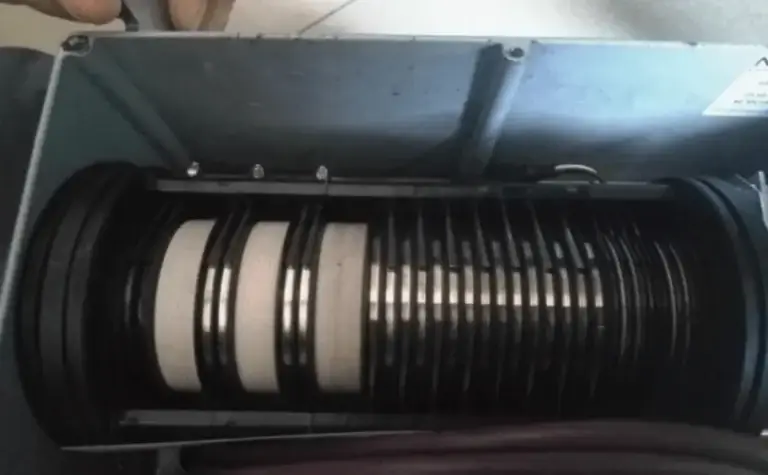
Graphite-Alloy Carbon Brushes
Cost-Effective Power: Blending elastic materials with graphite-metal alloys creates a highly resilient, high-amperage contact solution perfect for smooth channels.
Downside: Mechanical friction produces conductive dust and wear debris, requiring strict periodic cleaning. They are generally unsuitable for high-speed data transmission.
Best Practices for Electrical Slip Ring Maintenance and Cleaning
Routine servicing extends the operational lifecycle of your electrical collector rings and safeguards your data lines. Always remember that certain sealed slip ring models do not support field brush or block replacement.
Step-by-Step Slip Ring Maintenance Protocol
- CRITICAL SAFETY FIRST: Always isolate and lock out both main and backup power supplies before opening the enclosure. Check and verify torque specifications on all structural bolts during reassembly.
Debris Inspection: Check the tracking channels and brush assemblies for fibers or coarse particulate matter. Foreign contaminants can lift the brush, causing signal dropouts or destructive electrical arcing.
Brush Block Replacement: Swap out any warped, bent, or physically damaged brush blocks immediately. When installing a new block, realign the wires precisely with their corresponding V-grooves, apply thread-locking compound to the screws, and torque them to at least 7Nm.
Controlled Track Cleaning: Minimize chemical washing, as excessive cleaning can alter contact film and disrupt data communication. When necessary, lay the unit flat, spray anhydrous ethanol onto the tracks, and rotate the assembly evenly to lift contaminants.
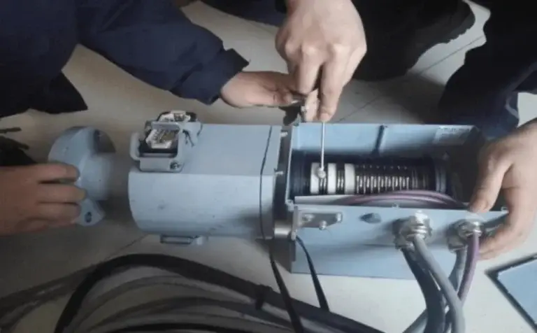
Debris Removal: Gently clear out stubborn sludge accumulation beneath the carbon brushes using a soft-bristled brush. Work in pairs to turn the rotor at a steady, uniform pace to avoid bending the delicate wires.
Drying and Lubrication: Use a heat gun to dry the assembly thoroughly while rotating it. Apply exactly one drop of specialized lubricant per track; over-lubricating attracts airborne dust and degrades signal quality.
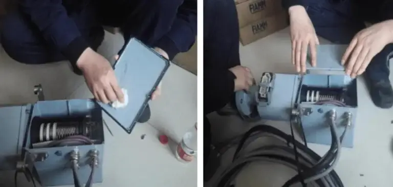
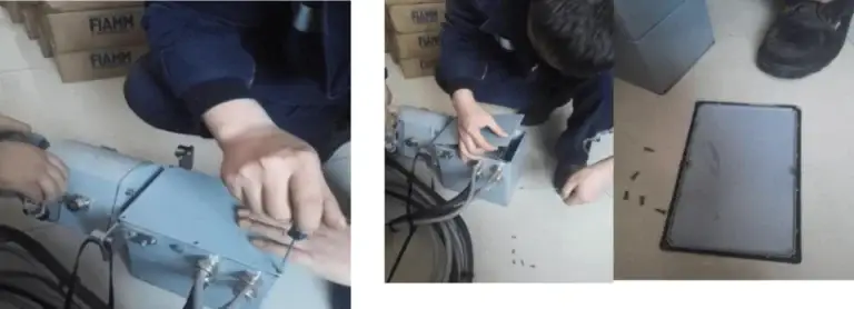
Enclosure Resealing: Wipe down the housing cover with anhydrous ethanol. Inspect the rubber seals, replace them if degraded, apply fresh sealant to the screw threads, and tighten them in a cross-diagonal pattern to prevent dust ingress.
Industrial Slip Ring Troubleshooting FAQ
A: Follow this systematic diagnostic path:
Inspect the surge protective devices (SPDs) within the safety chain loop.
Test the safety chain loop relays for proper switching.
Verify the continuity and wiring connections across the entire safety circuit.
Ensure all cables inside the hub control cabinet are securely tied down and not swaying during rotation.
If three related faults trip simultaneously, inspect the core slip ring assembly for an internal open circuit or short.
Q2: How do I resolve a system error indicating the hub slip ring encoder speed exceeds its limit?
A: Address this issue by checking three main areas:
Check the physical mounting of the slip ring. The anti-rotation torque arm/support rod must be secure, yet allow slight, flexible play in the rotational direction.
Diagnose the slip ring encoder for hardware faults or optical misalignment.
Verify that the rotor blade zero-position calibration is perfectly accurate.
Summary & Next Steps
Selecting the proper friction pair material and following a strict, torque-verified maintenance schedule are key to avoiding signal loss and extending the life of your rotary systems. Debris management, precise brush alignment, and controlled lubrication keep your operations running smoothly without unexpected breakdowns.
Here is a Further Slip Ring Engineering Guide for Design, Selection and Manufacturing Reference.
Looking for high-performance rotary solutions tailored to your specific application? Contact our engineering team today for expert advice on choosing slip rings, material customization, and optimizing your system’s performance.